Star sensors measure star coordinates in the spacecraft frame and provide attitude information when these observed coordinates are compared with known star directions obtained from a star catalog. In general, star sensors are the most accurate of attitude sensors, achieving accuracies to the arc-second range.
© Copyright 2010 www.spacealliance.ro
Introduction
Researchers in the field of spacecraft dynamics and control are concerned with creating accurate and understandable physical models of satellites. These simulations help to verify principles of motion and to test control designs for both attitude and orbit control.
Within this array of packages, there are specialized applications that may appeal to different aspects of spacecraft modeling, including power, communications or attitude.
This chapter is related to the star tracker system and intends to provide an overview of the major topics in this field.
- The star tracker control
- Star image processing
- Star pattern identification
- Attitude estimation
Star sensors measure star coordinates in the spacecraft frame and provide attitude information when these observed coordinates are compared with known star directions obtained from a star catalog. In general, star sensors are the most accurate of attitude sensors, achieving accuracies to the arc-second range. This impressive capability is not provided without considerable cost however. Star sensors are heavy, expensive, and require more power than most other attitude sensors. In addition, computer software requirements are extensive, because measurements must be preprocessed and identified before attitude can be calculated. Star sensors also suffer from both occultation and interferences from the Sun, the Earth and other bright sources. In spite of these disadvantages, the accuracy and versatility of star sensors have led to applications in a variety of different spacecraft attitude environments.
Overview
Star sensing and tracking devices can be divided into three major classes: star scanners, which use the spacecraft rotation to provide the searching and sensing function; gimbaled star trackers, which search out and acquire stars using mechanical action; and fixed head star trackers, which have electronic searching and tracking capabilities over a limited field of view. Sensors in each of these classes usually consists of the following components as illustrated for a V slit star scanner: a Sun shade; an optical system ;an image definition device which defines the region of the field of view that is visible to the detector; the detector; and an electronics assembly. In addition, gimbaled star trackers have gimbal mounts for angular positioning.
Stray light is a major problem with star sensors. Thus, an effective Sun shade is critical to star sensor performance. The light baffles are usually employed to minimize exposure of the optical system to sunlight and light scattered by dust particles, jet exhaust, portions of the spacecraft itself, Earth albedo and moonlight. Even with a well designed Sun shade, star sensors are typically inoperable within 30 to 60 deg of the Sun.
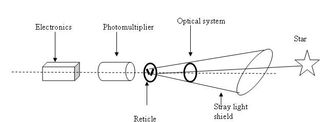 Simplified diagram of a V slit star sensor
The star sensor optical system consists of a lens which projects an image of the star field onto the focal plane. The major goals for the lens are to assure the convergence of the star light into the focus of the optical system, to provide the desired wavelength filtering of the star’s light such that the stars can be discriminated by their spectral characteristics and to ensure a thermal stability. The image definition device selects a portion of the star field image in the sensor’s field of view (FOV) which will be visible to the detector- known as the instantaneous field of view (IFOV). The image definition device may be either a reticle consisting of one or more transparent slits etched on an otherwise opaque plate, or an image dissector tube in which the IFOV electronically scans the FOV. The detector transforms the optical signal (whatever light is not blocked by the image definition device) into an electrical signal. There are basically two types of detectors: one is so called image dissector tube (which consists of a photocathode located in the focal plane of the optical system, an image dissector and a photomultiplier) and the second one is the charge coupled device (a solid state integrated circuit, built as a matrix of photo-sensitive semiconductors elements called pixels). Finally, the electronics assembly filters the amplified signal received from the photomultiplier and performs many functions specific to the particular star sensor.
Star scanners used on spinning spacecraft are the simplest of all star sensors because they have no moving parts. The image definition device employed by this type of sensor consists of a slit configuration, such as the V slit. The spacecraft rotation causes the sensor to scan the celestial sphere. As the star image on the focal plane passes a slit, the star is sensed by the detector. If the amplified optical signal passed from the detector to the electronics assembly is above a threshold value, then a pulse is generated by the electronics signifying the star’s presence. The accuracy of this sensor is related to the width of the slits and is typically on the order of 0.5 to 30 arc-minutes, although more accurate models exist.
The interpretation of star scanner measurements becomes increasingly difficult as spacecraft motion deviates from a non-nutating, uniformly spinning rigid body. The nominal spin rate has a direct influence on the success of interpretation of star scanner data. Problems of noise and the generation of false star crossing signals are greater in this case. Therefore, interpretation of the star scanner data is virtually impossible during the periods when the spin rate changes rapidly.
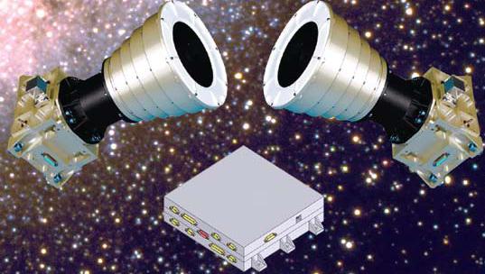
Gimbaled star trackers illustrated in the next figure are commonly used when the spacecraft must operate at a variety of attitudes. This type of tracker has a very small optical FOV (usually less than 1 deg). The gimbal mounts, however, give the sensor a much larger effective FOV. Gimbaled star trackers normally operate on a relatively small number of target stars.
Many different kinds of image definition devices are used in gimbaled star trackers to determine the position of the star with respect to the center or null position in the small FOV. The electronics assembly causes the gimbals to move so that the star image remains centered in the small FOV. The star’s position is then given by the gimbal angle readout positions. Some image definition devices employ an optical or electronic scan of the small FOV to provide star position information. For example, small FOV image dissector tubes may perform this function. Another type of scanning device is an optical wedge slit system. A rotating optical wedge causes the star image to be deflected past an L shaped slit. As the wedge rotates the image of the star follows a circular path over the L slit. The optical wedge is designed so that the radius of the circle grows as the star image diverges from the null position. The electronics assembly determines the position of the star with respect to null by comparing the time difference between slit crossings and the rotation phase of the optical wedge.
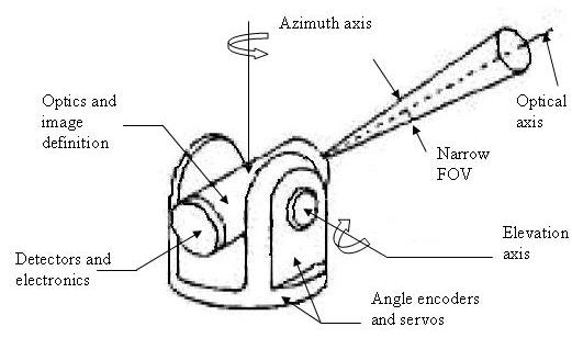 Gimbaled star tracker
One type of gimbaled star tracker does not use an image definition device at all, but rather reflects a defocused star image onto four photomultipliers in a square array. The star’s position is determined by comparing the output signals of the four photomultipliers. This system has the advantage of simplicity. However it suffers from disadvantages: temperature variations and changes in photomultiplier characteristics due to aging may introduce systematic biases; non-uniform background light or the presence of a second star within the small FOV causes serious errors.
Errors in determining the star position with respect to null and gimbal angle readout errors affect the overall gimbaled star tracker’s accuracy. Typical accuracies range from 1 to 60 arc-seconds, excluding tracker misalignment. A major disadvantage of gimbaled star trackers is that the mechanical action of the gimbals reduces their long term reliability. In addition, the gimbal mount assembly is frequently large and heavy.
Spacecraft which maintain an inertially fixed direction commonly employ gimbaled star trackers which have a unique target star. The position of Polaris and Canopus near the north celestial and south ecliptic poles, respectively, make these two stars particularly useful. A serious disadvantage of unique star trackers is that they may occasionally track either the wrong star or particles scattering stray light, such as paint chips from the spacecraft.
Fixed head star trackers use an electronic scan to search their field of view and acquire stars. They are generally smaller and lighter than gimbaled star trackers and have no moving parts. A charge coupled device star tracker is essentially an optical system combined with a digitally scanned array of photosensitive elements whose output is fed to a microprocessor. Such a tracker operates by integrating a charge pattern corresponding to the image of the star field on the focal plane of the optical system. The charge pattern is then read out serially line by line to an analog to digital converter and then to a microprocessor.
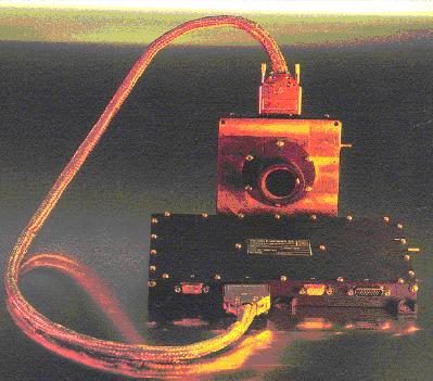
A typical fixed head star tracker using an image dissector tube is shown here.
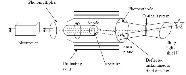 Cutaway diagram of image dissector tube star sensor
The photocathode contains the star field image created by the optical system. An electron replica of this image is deflected past a fixed receiving aperture by the magnetic deflecting coils. This aperture defines a small IFOV (usually in the arc-minute range) on the photocathode and hence on the star field image.
Although this aperture does not move in the dissector tube, the IFOV scans across the fixed image as the current through the deflection coils is varied. An image dissector searches its FOV for stars by moving the IFOV in a search pattern such as a right to left staircase retrace pattern or a center to edge rosette pattern. When the detector finds a visual signal above a threshold value , the electronics assembly engages a track pattern The IFOV then moves in a small figure eight or square pattern so that the electronics assembly can locate the center of the star image. The IFOV will either remain in the tack pattern until the star is lost, or it will automatically resume searching after a predetermined time interval (depending on mission requirements and sensor electronics).
If a photomultiplier is placed after the receiving aperture of the image dissector in a fixed head star tracker, the instrument is referred to as an analog image dissector. Alternatively if a photoelectron counter is used the instrument is called a photon counting image dissector.
Image dissectors are subject to errors from stray electric and magnetic fields.
Electric and transverse magnetic field effects can be reduced by shielding. However it is more difficult to shield against axial magnetic fields. Errors due to these effects become significant in the outer regions of a large FOV image dissector. Image dissectors have the advantage of high sensitivity, low noise and relative mechanical ruggedness.
The choices of field of view size and star magnitude sensitivity for any star sensor generally depend on the attitude accuracy requirements. A small FOV tracker can provide more accurate star positions than can a larger FOV tracker with comparable components. However a small FOV tracker must be sensitive to dimmer stars to ensure that enough stars are visible to it. Use of a larger FOV demands extensive pre-launch ground calibration for temperature, distortion, and magnetic effects as well as post-launch preprocessing of data to correct for these effects.
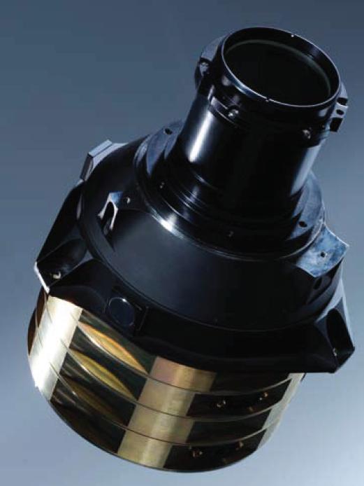
The following figure presents a star sensor equipped with a CCD detector.
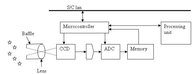 Star sensor components
The CCD or “charge couple devices” star trackers are the most popular nowadays because in comparison with the other sensors they have the highest value for the quantum efficiency parameter while they also cover a wide wavelength region as it will be later described.
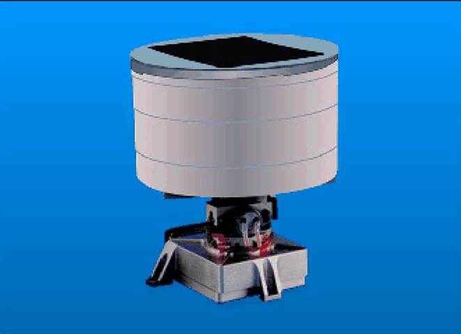
The following part will show in a comparative manner some of the commercial units available on the market.
 credit Terma Space
| Weight |
0.9 kg |
| Power consumption |
7W (22-34V) |
| Operating temperatures |
-40/+25 C |
| Data interface |
RS422 & MIL-STD-1553 |
| Field of view |
22 x 22 degrees |
| CCD |
1024 x 1024 pixels |
| Sun exclusion angle |
30 degrees |
| Accuracy |
<1 arc-seconds pitch, yaw
<5 arc-seconds roll |
| Slew rate |
0.5 deg/s full performance
2.0 deg/s reduced performance |
| Update rate |
4 Hz |
| Acquisition time |
3-5 seconds |
| Mission flown |
Cryosat, Aeolus, Nemo, DSX |
 credit NASA
| Weight |
0.29 kg |
| Power consumption |
4.5 W |
| Operating temperatures |
|
| Data interface |
|
| Field of view |
28.9 x 43.4 degrees |
| CCD |
576 x 384 pixels |
| Sun exclusion angle |
|
| Accuracy |
|
| Slew rate |
|
| Update rate |
5 Hz |
| Acquisition time |
|
| Mission flown |
Clementine |
- A-STR (autonomous star tracker)
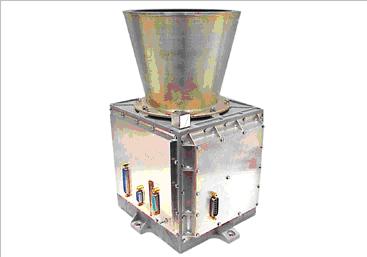 credit Galileo Avionica
| Weight |
3 kg |
| Power consumption |
8.9-13.5 (20-50V) |
| Operating temperatures |
-30/+60 C |
| Data interface |
RS422, MIL-STD-1553 |
| Field of view |
16.4 x 16.4 degrees |
| CCD |
512 x 512 pixels |
| Sun exclusion angle |
|
| Accuracy |
7 arc-seconds pitch, yaw
25 arc-seconds roll |
| Slew rate |
0.5 deg/s full accuracy
2 deg/s reduced accuracy |
| Update rate |
10 Hz |
| Acquisition time |
< 6 seconds |
| Mission flown |
Rosetta, Mars Express, Venus Express, Cassini, Stereo, Herschel, Planck etc |
 Credit Jena Optronik
| Weight |
4.5 kg |
| Power consumption |
|
| Operating temperatures |
-30/+55 C |
| Data interface |
RS 422, MIL-STD-1553B |
| Field of view |
13.8 x 13.8 degrees |
| CCD |
1024 x 1024 pixels |
| Sun exclusion angle |
|
| Accuracy |
<1 arc-second pitch, yaw
<10 arc-seconds roll |
| Slew rate |
<0.3 deg/s full accuracy
<2 deg/s reduced accuracy |
| Update rate |
|
| Acquisition time |
0.25 – 5 seconds |
| Mission flown |
Spaceway, MSV, WGS |
- FSC-701 flexible space camera
 Credit Ball Aerospace
| Weight |
5.83 kg |
| Power consumption |
16 W |
| Operating temperatures |
-20/+50 C |
| Data interface |
RS422, MIL-STD-1553 |
| Field of view |
22 x 22 degrees |
| CCD |
1024 x 1024 pixels |
| Sun exclusion angle |
30 degrees |
| Accuracy |
8.7 -89.2 arc-seconds |
| Slew rate |
8 deg/s |
| Update rate |
Up to 30 Hz |
| Acquisition time |
|
| Mission flown |
Calipso |